
Yup, that’s me standing next to the secondary coil for reference. This is a project I’ve been working on with a friend (David, UCLA class of ‘24) on-and-off since Fall 2019: to build the biggest and best Tesla coil, with a few criteria attached: 1) we need to be able to run it safely in my backyard, and 2) we want to be able to do it under $200. This coil, unlike the VTTC, uses a rotary spark gap as the switch to “drive” the circuit and excite oscillations. For building something of this scale, operating on high voltages and currents, challenges appeared when usually small effects came into play, and we had to be really careful with both the materials we used and how we constructed the device. We’ve paused progress due to COVID, but as it stands, we have the majority of the system assembled, we still need to prepare a proper grounding rod, and, after the system’s complete, we’ll start testing and tuning it slowly and carefully, and I’m hoping we’ll get to see first light in 2021.

If you want to make something powerful (read: helps you get really high voltages) on a low budget, microwave oven transformers (MOTs) might be your best bet. For this build we used 4 MOTs, which provide ~2000V at ~1000W and ~0.5A, in a voltage doubler circuit, for the Tesla coil’s power supply. Filters from microwave ovens were used as a safety measure, and capacitors added for filtering.
Testing out the power supply was pretty incredible-if I did my math right, with the voltage doubler with the MOTs and more multiplier stages added later, we could get around 20,000v with this supply. As an aside, there were a few resources that helped a lot in this project: Matt Behrend’s paper on Tesla coils, and DeepFriedNeon, a site with many coiling design guides and calculators, which were useful for helping us plan this build. Anyways, back to this-running this supply was actually quite scary with both how loud it was and the huge output-and it also brought a few important problems to my attention. One, we’d need a way to safely discharge the circuits we were testing, and two, messing with this kind of high power required a LOT of care and attention. We had a flaw in insulation, for example, and after testing the supply we noticed there had been arcing happening which burned the base-it could have been a lot worse, and this was a signal that we had to triple-check everything.
Next step after the power supply was constructing the spark gap. We went with an asynchronous rotary spark gap, this was chosen because it allowed us to use a smaller capacitor-and also so that the circuit could handle more higher-power pulses at levels approaching but not above that which might normally be harmful, potentially meaning that we could run the coil at a higher power level than if we used a synchronous spark gap. We used an old motor (David says it might have been from a washing machine) to spin the rotating electrode, and screws for the stationary electrodes, originally using a motor controller that we made ourselves. This picture was from us testing the motor and controller.
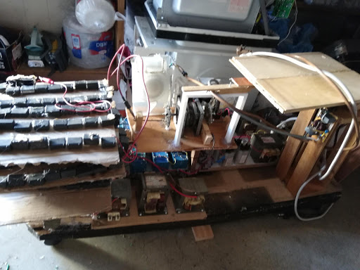
For the primary capacitor, we made a multi-mini capacitor bank using 0.33 uF 800vAC/1200vDC capacitors ordered from Taobao. The capacitance of the bank is 19 nF. We added a high-voltage meter for monitoring under it, and began putting everything together. The rotary spark gap can be seen in this photo as well, with 2 stationary electrodes in place so far.


After all that, it was now time to make the secondary coil, which presented us with quite a challenge. For a coil of the height we wanted, we needed to wind it around something, so, without any coilforms or other cylindrical objects of that size lying around, we instead tried to make one. We had a lot of thin PVC pipes, and the idea was perhaps we could arrange them in a circle and wind magnet wire around this circle of standing PVC pipes to make the secondary coil. So, we designed and 3D printed mounts to hold the PVC pipes upright, then began winding wire, but this didn’t go very well as the shape wasn’t reinforced, and the coil began to lean heavily.
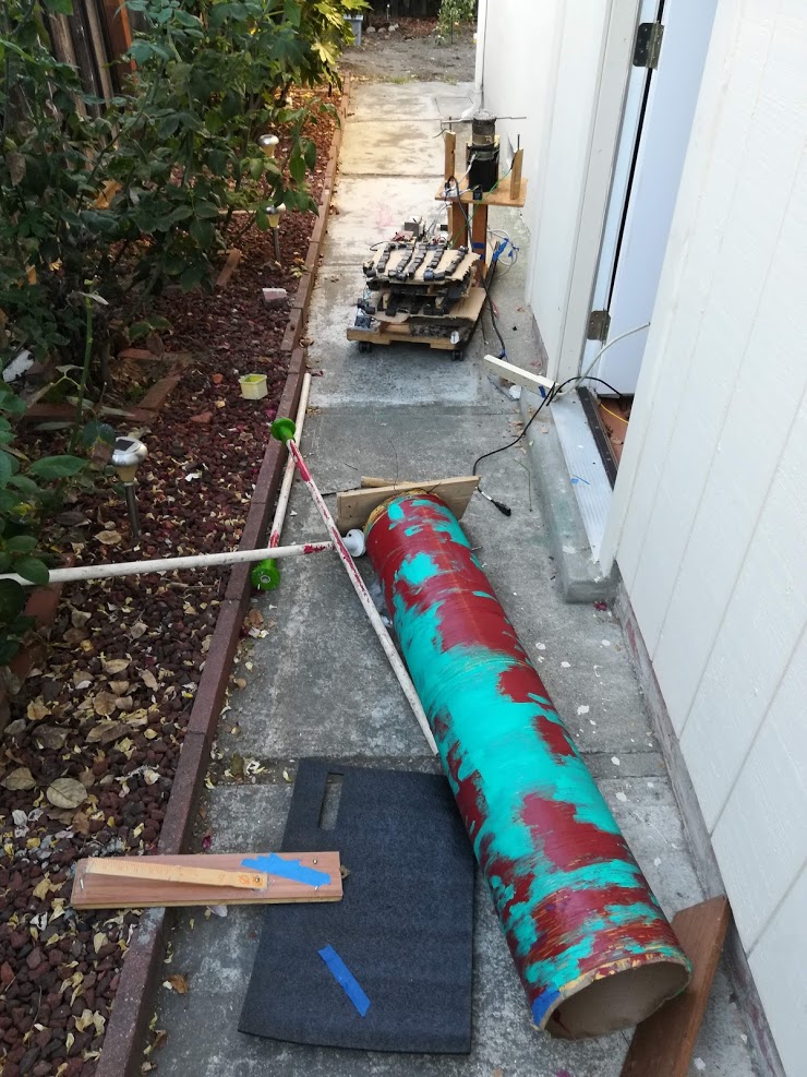
It turned out, though, that we probably didn’t need to do that, because thankfully “Cardboard Concrete Building Form Tubes”, as described by my local hardware store, exist-they’re like molds for making concrete pillars, and we were able to obtain one for our secondary coil. Winding coils, especially when they’re almost 6 ft tall and you’re using 24 AWG wire, is really tedious, so we built a rig which placed the coil horizontally with a slowly-spinning motor on 1 end and a cap/holder on the other, to help us out. After finishing the secondary we made a massive “pancake” primary coil as well, and installed the primary and secondary coils on their own wheeled platform. We weren’t able to test if this has any effect on the circuit, but since this coil was absolutely enormous and hard to move, I tried having the wires from the coils come to clips, which could be attached to solid terminals to connect them to the rest of the circuit. That’s where we’re currently at as far as this build goes!