
The robot Team 670 built for 2020’s FRC game Infinite Recharge was one of the most complex designs we ever attempted. It wasn’t because any single mechanism-instead, the complexity arose from the many connections between subsystems of the robot. Relaying balls from the intake to indexer to shooter required the subsystems on this path to work together flawlessly: timing was important, and jams needed to be prevented in any way possible, otherwise the robot would be unable to score balls. The way these systems depended on each other meant we had to get creative to find ways of dealing with issues wherever and whenever they were most likely to appear. As Tech Lead, leading the team’s work in handling this challenge on the software and control side was my job, while I also contributed to design and testing.
Before all that though, you have to see this thing in action-the final (well, current iteration, anyways-it wasn’t going to be final, but COVID changed that) system was rather…mercurial… to say the least, given its complexity, but it was pretty fun. (Also because editing this following video was hilarious and a long time in the making-way back in November 2019, we as build team leads went “yo, we have to make a reveal video, and we’re going to set it to Psy’s ‘Gentleman’ song, it will be epic.”)
This video is a quick and nice overview of how our robots’ systems all work together. Apologies for the sped-up audio- I originally made this as an awards submission for KLA Robogames 2020. It paid off, though: this video was what won our team the Creativity Award.
Alright, so this was my favorite thing to work on, and also the thing that caused me the most sleepless nights and all-nighters through build season. The biggest piece of robot development on my part was architecting a new framework for robot code that would hopefully make dealing with this kind of complexity, with interconnected and interdependent subsystems, more straightforward. One big problem with the current control system was that if there was a problem in some subsystem, one could still run something that would use the broken subsystem, potentially causing more issues. We needed something to automatically manage checking subsystems’ health, and handle whether an action should be done or not. This way, the robot code as a whole wouldn’t completely crash if something malfunctioned, and it would prevent actions associated with that missing element from being scheduled at all. This was built on top of the libraries we used (WPILib), it wasn’t completely new, but it allowed for better separation of concerns. Not only would this be useful now, but I worked to organize it so it’d be useful as a codebase/library for the team in the future too.
I made a super nifty writeup about MustangSystem here, check it out!

One innovation we made on the design side was to cover basically every surface that a ball might come in contact with, with brushes and rollers. Why? We found that the balls were incredibly sticky. If they rubbed on a surface while moving, it was quite likely that they’d get stuck and jam up in the robot. In our indexer, to keep balls moving along as the revolver turned, we cut nylon tubing into rollers, placing them all around the indexer’s sides-we tested different distances, numbers of rollers, and placements to try and absolutely minimize the number of places where a ball could jam. The revolver’s arms, which separate the chambers, were also roller-ed, and since we noticed balls often jammed on entering the revolver when they hit its edges, we put nylon rollers there too. On bearings. This helped prevent many common jams without needing any active mechanisms-which was really nice, since we were running low on slots for motors.
A common issue was that balls wouldn’t be centered when entering the indexer’s bottom chamber, off the conveyor. If the indexer began turning, the ball often got smooshed on the side, causing a big jam. We needed something to force balls to center, but we ran out of room to add motors. Solution: a pneumatic piston to punch the incoming ball, forcing it to center. Controlling this was difficult, as the “punch” had to be timed carefully so as not to interfere with or slow down the indexer’s turning, while also hitting the ball exactly on entering the indexer and in the right place-it took a lot of adjusting to find both the timing and the positioning of the piston. Then, we realized that 1 piston wasn’t enough-sometimes if it was jostled, it would push the ball slightly off-center and into a jam, so we added another piston mirroring it across the conveyor. We also found it was necessary for the pistons to punch whenever an occupied chamber rotated to the bottom, to further reduce jams.
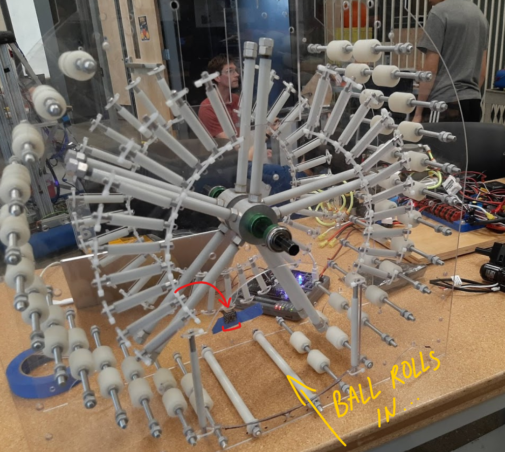
For the indexer to turn safely, it had to check that the ball was all the way in. I originally considered using beam break sensors or a force-sensitive resistor on the indexer’s back wall. However, there wasn’t a good place for mounting a FSR (because we minimized flat surfaces to reduce jam risk), and the conveyor and indexer arms got in the way of placing a beam break. Instead I used a time of flight sensor, placed low enough to be out of the arms’ way. It measured a distance to an object blocking its beam, which allowed me to check for 3 values: 1) minimum distance between ball and sensor that’s considered “fully in” (in other words, as in as you can get)-20mm; 2) maximum “fully in” distance-50mm; 3) distance from the ball to the indexer’s back where the “puncher” pistons could fire to center the ball-110mm. Once the sensor registered between 20mm-50mm, indicating that a ball was in, this was the signal that the indexer was ready to move.

Besides the pistons, we also have a tunnel over the conveyor from the intake to indexer-both serve the purpose of centering balls, making sure they stick to the main path and don’t jam. We again wanted to reduce any chance a moving ball had of contacting some surface and potentially sticking to it (jam hazard…) so brushes were added under the tunnel-I remember our first attempt used a door-brush-seal. I organized a group to test out brushes of different lengths and figure out how and where to place them. We also had to figure out the shape of the structure we’d be mounting brushes on-hence the Cup Noodles box taped over for prototyping purposes-eventually we settled on a polycarbonate sheet bent to arch over the conveyor.

I wanted to automate unjamming-on the field, it’s often impossible to resolve jams in time to prevent issues. For the intake, a common place for jams, one could unjam by running it in reverse. To automate that, we need an indicator to use as a signal to reverse. When the intake jams, current drawn by its motor spikes, and we can read this data in. So, when we detect a current spike on the motor, then we assume the intake’s jammed, and we reverse it until the spike drops. However, we found another issue: how do we see if an observed spike is actually from a jam? We observed that current could spike in non-jam situations too-when the intake motor starts moving and when balls contact surfaces normally. I looked at how long each spike was present for by checking current over a time interval: if we found the current drawn was really high over 10 cycles, then there probably was a jam and the intake should be reversed-versus if it only lasted over 3 cycles, then it could probably be ignored.